


Please Leave Us A Message
Privacy statement: Your privacy is very important to Us. Our company promises not to disclose your personal information to any external company with out your explicit permission.
 February 19, 2022
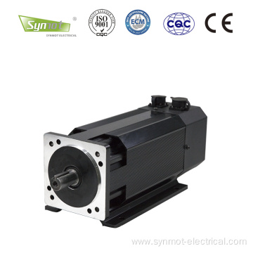
A Servo Motor is an engine that controls the operation of a mechanical component in a Servo System, and is an auxiliary motor indirect transmission. The servo motor can control the speed and position accuracy very accurately, and can convert the voltage signal into torque and speed to drive the control object. The servo motor rotor speed is controlled by the input signal and can react quickly. It is used as an actuator in the automatic control system, and has the characteristics of small electromechanical time constant, high linearity, and starting voltage, which can receive the received electrical signal. Converted to an angular displacement or angular velocity output on the motor shaft. Divided into two major categories of DC and Ac Servo Motor, its main feature is that when the signal voltage is zero, there is no rotation phenomenon, and the rotation speed decreases uniformly with the increase of torque.
The DC servo motor is actually a separately excited DC motor, and its structure and principle are the same as those of the conventional separately excited DC motor, except that the output power of the DC servo motor is small.
Armature control: The control signal is applied to the armature winding, and the magnitude and direction of the rotor speed are controlled by changing the magnitude and polarity of the control signal. Magnetic field control: The control signal is added to the field winding for control.
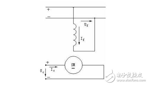
When the DC servo motor is used for armature control, the armature winding is the control winding, and the control voltage is directly applied to the armature winding for control. There are two types of excitation methods: one is excited by DC current by excitation coil, which is called electromagnetic DC servo motor; the other uses permanent magnet as magnetic pole, and the excitation winding is omitted, which is called permanent magnet DC servo motor.
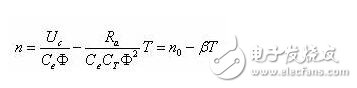
(1) Mechanical properties
The control voltage Uc is changed, and the slope of the mechanical characteristic is constant, so the mechanical characteristic is a set of parallel straight lines.
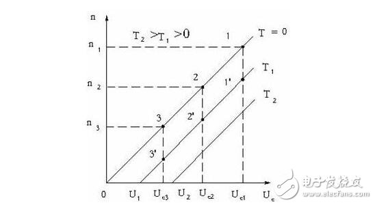
(2) Adjustment characteristics
The adjustment characteristic refers to the relationship between the rotational speed n of the motor and the control voltage Uc under a certain torque.
It can be seen from the adjustment characteristics that when the torque is constant, such as the enhanced control signal Uc, the rotational speed of the DC servo motor increases and is in a proportional relationship; otherwise, the weakening control signal Uc is weakened to a certain value U1, the DC servo motor stops rotating, that is, When the control signal Uc is less than U1, the motor is blocked, and the motor must be able to rotate. The control signal Uc must be greater than U1, so U1 is called the starting voltage.
The mechanical characteristics and adjustment characteristics of the DC servo motor during armature control are linear, and there is no "rotation" phenomenon.
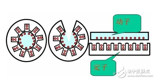
The AC servo motor is actually a two-phase asynchronous motor, so it is sometimes called a two-phase servo motor. There are two-phase windings on the stator of the motor, one phase is called excitation winding f, connected to AC excitation power supply Uf, the other phase is control winding c, and the control voltage Uc is connected. The two windings are spatially different from each other by 90°, and the excitation is performed. The voltage Uf and the control voltage Uc have the same frequency.
The working principle of an AC servo motor is similar to that of a single-phase asynchronous motor. When the field winding of the AC servo motor is connected to the field current Uf, if the control voltage Uc applied to the control winding is 0 (ie, no control voltage), the pulse magnetomotive force is generated, and the pulse magnetic field is established. The motor has no starting torque;
When the control voltage applied to the control winding is not zero, and the generated control current is different from the phase of the excitation current, an elliptical rotation is established.
The magnetic field (if the phase difference between Ic and If is 90°, it is a circular rotating magnetic field), so the starting torque is generated and the rotor of the motor rotates. If the motor parameters are the same as for a normal single-phase asynchronous motor, then when the control signal disappears, the motor speed will decrease, but it will continue to rotate. The out-of-control phenomenon in which the servo motor continues to rotate after the control signal disappears is called "rotation".
The "rotation" can be eliminated by increasing the rotor resistance.
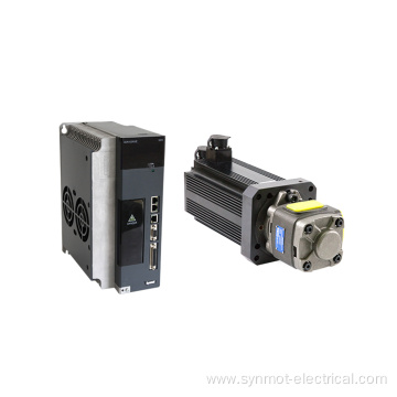
DC servo motor drive moduleSince the DC servo motor is actually a small-capacity separately excited DC motor, various drive modules of the ordinary DC motor can actually be used to drive the DC servo motor. However, in general, the capacity of the DC servo motor is much smaller than that of the ordinary drive DC motor, that is, the armature drive capacity is small, and the drive module of the ordinary DC motor is usually applied to a medium-large capacity motor as an electric drive. In addition, as the servo motor has special requirements for linearity, sensitivity and rapidity of its control, there are corresponding requirements for the dynamic and static characteristics of the drive module. Therefore, DC servo motors often need to have their own dedicated drive modules. A typical drive circuit for a DC servo motor is actually a DC linear power amplifier that directly drives the DC servo motor by voltage and power amplification, as shown in Figure 1. Therefore, the drive module of the DC servo motor is also called DC servo amplifier module.
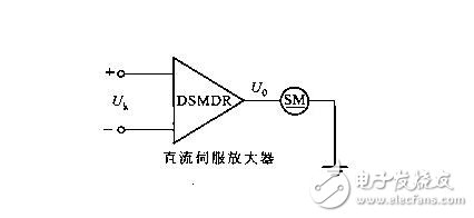
(1) Basic form and principle of DC servo motor drive module
In principle, the DC servo motor drive module is also composed of two parts: a power circuit and a control circuit. There are two basic forms of power circuit principle. These two basic forms are called voltage control type (DSMDRV) and current control type (DSMDRC).
(2) Drive module DSMDR consisting of power electronics
A power control type bidirectional driving module with current limiting function can be constructed by using power electronic components.
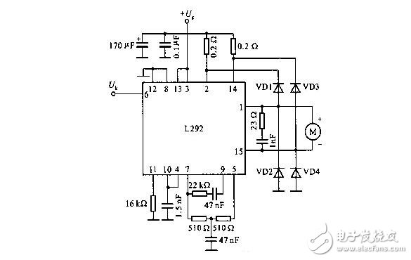
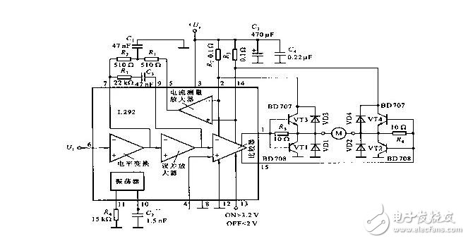
(3) Using a power integrated circuit to form a DSMDR driver module
Since DC servo motors are usually low voltage and low power. Therefore, some general-purpose power integrated circuits can be used to form a DC servo amplifier to directly drive a DC servo motor. In addition, there are currently dedicated power integrated circuits dedicated to driving DC servo motors on the market. Such integrated circuits have a large output current capability and it is very simple and easy to use them to form a DC servo amplifier.
The control signal is given by the computer control system, and the DC servo motor is driven through the interface and the power amplifier circuit.
Power amplifier circuits, also known as power amplifiers, currently have two main types:
(1) Thyristor power amplifier
(2) Transistor pulse width modulation (PWM) power amplifier.
1, PWM transistor power amplifier works
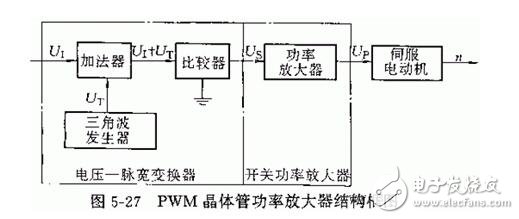
(1) Voltage-pulse width converter
Function: According to the control command signal, the pulse width is modulated, and the pulse signal with the width varying with the command is used to control the on-time of the high-power transistor to realize the control of the voltage across the armature winding.
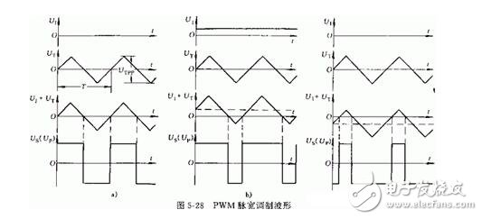
(2) Switching power amplifier
Function: Amplify the signal Us outputted by the voltage-pulse width converter, and output a signal Up with sufficient power to drive the DC servo motor.
Switching power amplifiers are often constructed using high power transistors. According to the control voltage waveform applied by the base of each transistor, it can be divided into three modes: unipolar output, bipolar output and limited unipolar output.
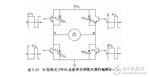
2. Mathematical model of PWM transistor power amplifier
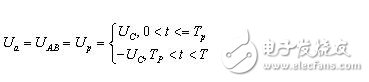
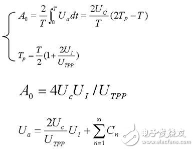
If the turn-on voltage drop of the transistor in the power amplifier circuit is ignored, the magnitude of UP is equal to the power supply voltage UC. Let the triangle wave period be T and the positive pulse width of US be TP, then the voltage Ua across the armature winding in one cycle is:
Expand into a Fourier series and get:
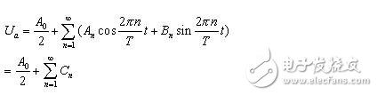
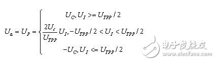
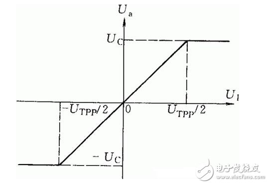
Since the switching frequency of the transistor (i.e., the frequency of Us) is typically higher than 1000 Hz, which is much higher than the frequency band of the DC servo motor, all harmonics (i.e., the AC component) will be attenuated by the low pass filtering of the motor. Thus, the AC component in the equation is negligible, which is simplified to Ua=2UcUi/UTpp. Taking into account the limiting characteristics of the PWM transistor power amplifier, the mathematical model can be obtained as follows:
3. Problems that should be paid attention to when designing the power amplifier circuit
Switching frequency selection
(1) The switching frequency should cause the motor shaft to vibrate to overcome static friction and improve the operating characteristics, but the maximum angular displacement of the micro-vibration should not exceed the allowable angular position error.
(2) The switching frequency should be chosen to be high enough to make the motor armature inductance large enough to reduce the effects of high frequency power consumption and AC components generated in the motor.
(3) The switching frequency should be higher than the resonant frequency of any component in the system to prevent resonance.
High power transistor selection
The high-power transistor operates in the switching state, and the allowed switching frequency must be greater than the switching frequency, and the switching characteristics are better, the voltage drop after the conduction is small, and the reverse withstand voltage is high to ensure the performance of the driving circuit and the motor.
The above is the Analysis of DC servo motor and AC servo motor, DC servo motor drive module analysis we have listed for you. You can submit the following form to obtain more industry information we provide for you.
You can visit our website or contact us, and we will provide the latest consultation and solutions
Send Inquiry
Most Popular
lastest New
Related Products
Send Inquiry

Privacy statement: Your privacy is very important to Us. Our company promises not to disclose your personal information to any external company with out your explicit permission.
Fill in more information so that we can get in touch with you faster
Privacy statement: Your privacy is very important to Us. Our company promises not to disclose your personal information to any external company with out your explicit permission.